Resistance (Symbol: R or r): Relationship between Voltage & Current
Definition of Resistance:
- Resistance (denoted as R) is the measure of how much a component or material resists the flow of electric current. It is measured in Ohms (Ω). Symbol of resistance is shown in Fig. 1.
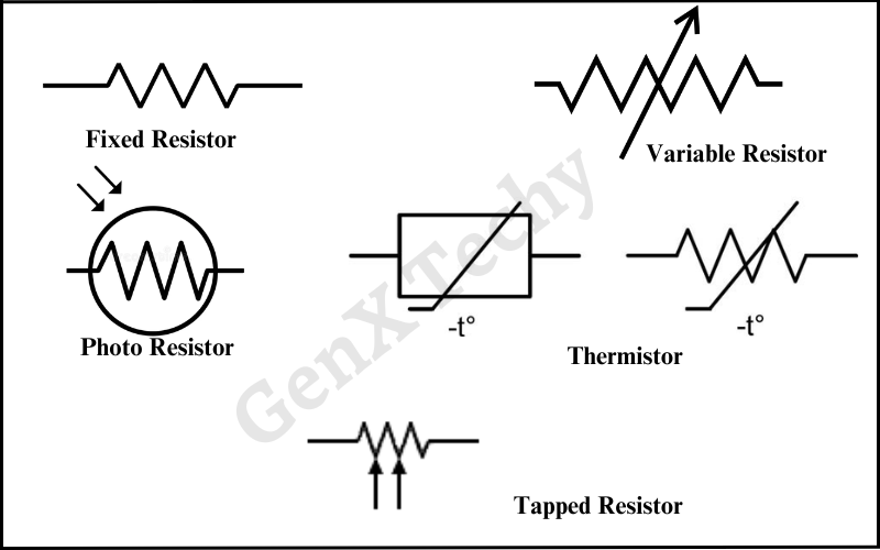
Fig 1: Symbol of Resistances
Ohm’s Law:
- Ohm’s Law states that the current (I) passing through a conductor between two points is directly proportional to the voltage (V) across the two points and inversely proportional to the resistance (R) of the conductor.
Mathematically, Ohm’s Law is expressed as:
V=I×R
Where,
- V is the voltage across the conductor (measured in volts, V),
- I is the current through the conductor (measured in amperes, A),
- R is the resistance of the conductor (measured in ohms, Ω).
Formula for Resistance
The resistance of a material is given by the formula:

Where,
- R is resistance,
- ρ is the resistivity of the material (measured in Ohm-meters, Ω·m),
- L is the length of the conductor,
- A is the cross-sectional area of the conductor.
Factors Affecting Resistance:
- Material: Different materials offer different levels of resistance. Conductors (like copper) have low resistance, while insulators (like rubber) have high resistance.
- Length: The longer a conductor, the higher the resistance.
- Cross-sectional area: A thicker conductor has less resistance because it allows more current to flow.
- Temperature: For most materials, as temperature increases, resistance increases (though some materials behave differently, like semiconductors).
Resistors:
A resistor is an electronic component designed to provide a specific amount of resistance in a circuit. They are used to control current flow, divide voltage, or limit the power delivered to certain components.
Types of Resistors:
Fixed Resistors: These resistors have a specific resistance value that doesn’t change. Fixed type resistors are further classified as Carbon-composition, Wire-wound, Metal film, etc. Table 1, shows the characteristics of few fixed resistors.
Table 1: Type and characteristics of Fixed Resistors
| Type of Resistors | Available Ranges | Tolerance | Temperature Coefficient | Maximum Power |
|---|---|---|---|---|
| Carbon Composition | 1Ω – 22 MΩ | 5 – 20% | 1 X 10⁻³ per °C | 2 W |
| Wire-Wound | 1Ω – 100 KΩ | 0.0005% | 5 X 10⁻⁶ per °C | 200 W |
| Metal Film | 0.1Ω – 104 MΩ | 0.005% | 1 X 10⁻⁶ per °C | 1 W |
| Carbon Film | 10Ω – 100 MΩ | 0 .5% | -1.5 X 10⁻⁴ per °C to 5 X 10⁴ per °C | 2 W |
Colour Coding of Resistors:
Resistors have coloured bands that indicate their resistance value, tolerance, and sometimes reliability. This system is called the resistor colour code.
- When you pick up a resistor, notice that the bands are nearer to one end; this end should be held in your left hand. Colour bands are always read from left to right.
- Four (4) bands on the resistor is an indication of General-purpose colour code and five (5) bands are used for precision colour code.
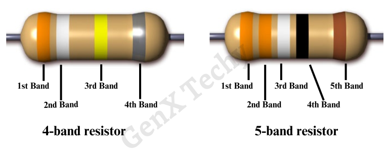
Fig 2: Colour band on Resistors
Colour Code Chart:
Each colour represents a specific digit, multiplier, or tolerance. The colours and their corresponding values are listed in Table 2.
Table 2: Colour code chart for Resistor bands
| Colour | Digit Value | Multiplier (Ω) | Tolerance (%) |
|---|---|---|---|
| Black | 0 | x100 | |
| Brown | 1 | x101 | ± 1% |
| Red | 2 | x102 | ± 2% |
| Orange | 3 | x103 | |
| Yellow | 4 | x104 | |
| Green | 5 | x105 | ± 0.5% |
| Blue | 6 | x106 | ± 0.25% |
| Violet | 7 | x107 | ± 0.1% |
| Gray | 8 | x108 | ± 0.05% |
| White | 9 | x109 | |
| Gold | x10-1 | ± 5% | |
| Silver | x10-2 | ± 10% | |
| No band | ± 20% |
(i) Resistance calculation for 4-Band Resistors:
- 1st Band: First digit of the resistance value.
- 2nd Band: Second digit of the resistance value.
- 3rd Band: Multiplier (the power of 10 the first two digits are multiplied by).
- 4th Band: Tolerance (accuracy of the resistor).
For example, a resistor with Red, Violet, Orange, and Gold bands:
- Red = 2 (1st digit),
- Violet = 7 (2nd digit),
- Orange = ×1,000 (Multiplier),
- Gold = ± 5% (Tolerance).
The resistance value is: 27,000 Ω ± 5% or, 27 KΩ ± 5%
(ii) Resistance calculation for 5-Band Resistors:
- 1st Band: First digit of the resistance value.
- 2nd Band: Second digit of the resistance value.
- 3rd Band: Third digit of the resistance value.
- 4th Band: Multiplier (the power of 10 the first two digits are multiplied by).
- 5th Band: Tolerance (accuracy of the resistor).
For example, a 5-band resistor with Brown, Black, Red, Orange, Brown:
- Brown = 1 (1st digit),
- Black = 0 (2nd digit),
- Red = 2 (3rd digit),
- Orange = ×1,000 (Multiplier),
- Brown = ±1% (Tolerance).
The resistance value is: 102,000 Ω ± 1% or, 102 KΩ ± 1%
- Variable Resistors (Potentiometers): A variable resistor, also known as an adjustable resistor or potentiometer, is a type of resistor where the resistance value can be adjusted manually to control the amount of current flowing through a circuit. This type of resistor is commonly used for tuning or calibrating electronic circuits and for controlling devices like volume knobs, dimmers, and speed controllers.
Types of Variable Resistors:
Potentiometer:
- A potentiometer has three terminals: two fixed terminals at the ends of a resistive element and a third terminal connected to a sliding contact (called a wiper).
- The wiper moves along the resistive element when the potentiometer is adjusted, changing the resistance between the wiper and either end terminal. This can be used to adjust voltage or current in a circuit.
- Applications: Volume control in audio devices, adjusting brightness in lamps, and controlling signal levels.
Rheostat:
- A rheostat is a two-terminal variable resistor used to control current. It is essentially a potentiometer but is used in high-power applications to adjust the current through a load.
- Applications: Fan speed controllers, light dimmers, and motor speed controls.
Trimmer (Trimpot):
- A trimpot is a small, adjustable resistor designed for occasional adjustment. It is used in circuits that require fine-tuning or calibration, and once set, it is rarely adjusted again.
- Applications: Calibration of oscillators, voltage reference circuits, and temperature compensation in various circuits.
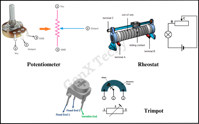
Fig 3: Types of Variable resistors
- Thermistors: A thermistor is a type of resistor whose resistance changes significantly with temperature. It is commonly used for temperature measurement, control, and compensation in various applications. The term thermistor is a combination of “thermal” and “resistor.”
Types of Variable thermistors:
There are two main types of thermistors, depending on how their resistance changes with temperature:
Negative Temperature Coefficient (NTC) Thermistor:
- For NTC thermistors, the resistance decreases as the temperature increases.
- They are typically used for temperature sensing and are more common than PTC thermistors.
- Applications: Digital thermometers, temperature sensors, inrush current limiters, and battery protection circuits.
Positive Temperature Coefficient (PTC) Thermistor:
- For PTC thermistors, the resistance increases as the temperature increases.
- PTC thermistors are often used in current-limiting applications or as overcurrent protection devices.
- Applications: Resettable fuses, overcurrent protection, heating elements, and de-icing circuits.
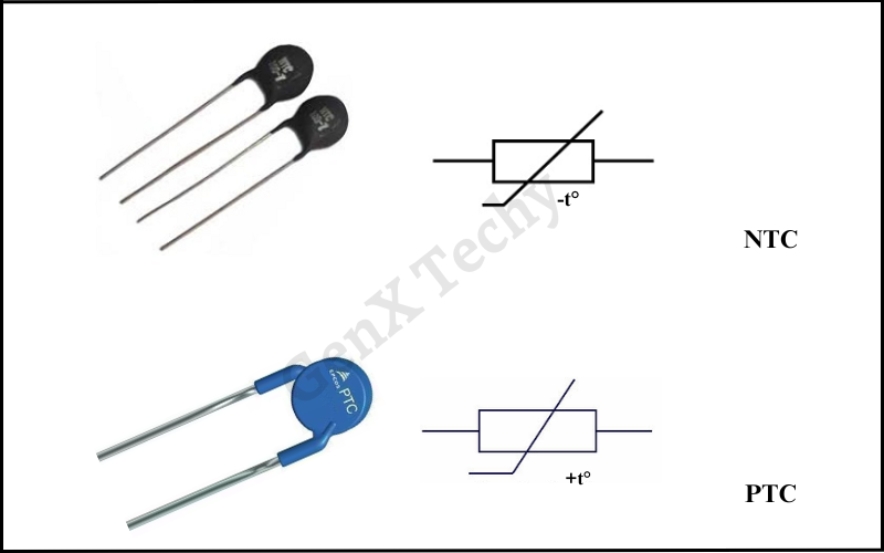
Fig 4: Types of Variable thermistors
Characteristics of Thermistors:
(i) High Sensitivity:
- Thermistors are highly sensitive to changes in temperature. Small temperature changes result in significant resistance changes, making them very effective for precise temperature measurements.
(ii) Non-Linear Behaviour:
- Thermistors exhibit non-linear behaviour, meaning their resistance does not change in a straight line with temperature. Instead, the change is more pronounced at certain temperatures.
- This non-linearity can be compensated using calibration techniques or look-up tables in electronics.
(iii) Temperature Range:
- NTC thermistors typically operate in a range of -50°C to +150°C, while PTC thermistors operate in ranges from 0°C to +200°C, depending on their specific application.