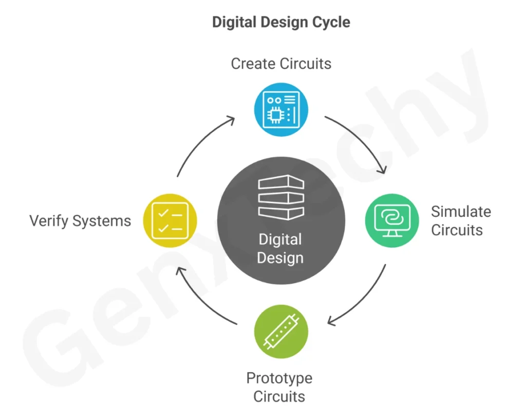
Digital design involves creating, testing, and implementing digital circuits using various hardware and software tools. These tools help engineers and students simulate, prototype, and verify digital systems before final implementation. Below is an elaborate explanation of the key tools and software used in digital design, including simulators and breadboards.Lorem ipsum dolor sit amet, consectetur adipiscing elit. Ut elit tellus, luctus nec ullamcorper mattis, pulvinar dapibus leo.
Digital Design Simulators
What is a Simulator?
Simulators are software tools that allow designers to model and test digital circuits virtually before building them physically. These tools are essential in modern digital design because they help identify design flaws before hardware implementation, saving time and resources.
Types of Simulators
1) Logic Simulators
Purpose: Simulate combinational and sequential logic circuits.
Examples:
(i) Logisim: A free, open-source tool for designing and simulating digital logic circuits. It supports basic gates, flip-flops, and memory elements.
Web-link: Logisim
(ii) CircuitVerse: A powerful simulator for digital logic with a drag-and-drop interface.
Features:
(i) Truth table generation.
(ii) Timing diagram visualization.
(iii) Support for hierarchical circuit design.
2) HDL (Hardware Description Language) Simulators
Purpose: Used for designing complex digital systems using languages like VHDL and Verilog.
Examples:
(i) ModelSim: ModelSim is a multi-language environment by Siemens (previously developed by Mentor Graphics) for simulation of hardware description languages such as VHDL, Verilog and SystemC, and includes a built-in C debugger.
Weblink: Modelsim
(ii) Xilinx Vivado Simulator: Used for FPGA-based designs.
(iii) Icarus Verilog: An open-source Verilog simulation tool.
Features:
(i) Supports behavioral, RTL, and gate-level simulation.
(ii) Waveform analysis for debugging.
(iii) Integration with FPGA synthesis tools.
3) Mixed-Signal Simulators
Purpose: Simulate both digital and analog components (e.g., ADC, DAC interfaces).
Examples:
(i) LTspice: Used for analog and digital mixed-signal simulations.
(ii) PSpice (by Cadence): Supports digital logic along with analog circuit simulation.
Features:
(i) Transient and DC analysis.
(ii) Cross-domain simulation (analog + digital).
4) FPGA/CPLD Simulators
Purpose: Simulate designs before programming them into FPGAs or CPLDs.
Examples:
(i) Xilinx ISE/Vivado: For Xilinx FPGA simulation.
(ii) Intel Quartus Prime: For Intel (Altera) FPGA simulation.
Features:
(i) RTL synthesis and timing analysis.
(ii) Post-place-and-route simulation.
Breadboards and Prototyping Tools
A breadboard is a physical tool used for constructing and testing electronic circuits without soldering. It consists of a plastic board with a grid of holes where components can be inserted and connected using jumper wires before final PCB fabrication.
(a) Traditional Breadboards
Structure:
(i) Made of plastic with interconnected metal clips.
(ii) Divided into power rails (for VCC/GND) and terminal strips (for components).
Advantages:
(i) Reusable and solderless.
(ii) Easy to modify circuits.
Limitations:
(i) Not suitable for high-frequency circuits (due to parasitic capacitance).
(ii) Limited to small-scale designs.
(b) Digital Trainer Boards
Purpose: Pre-built boards with built-in power supplies, switches, LEDs, and breadboard space.
Examples:
(i) Digilent Digital Discovery: A programmable logic trainer board.
(ii) Elbert V2 FPGA Trainer Board: For FPGA-based prototyping.
Features:
(i) Built-in clock generators.
(ii) Programmable I/O pins.
(c) PCB Prototyping Tools
Purpose: Convert breadboard designs into permanent PCBs.
Examples:
(i) KiCad: Open-source PCB design software.
(ii) Eagle (by Autodesk): Used for schematic capture and PCB layout.
Features:
(i) Auto-routing for traces.
(ii) Gerber file generation for manufacturing.
Integrated Development Environments (IDEs)
IDEs provide a complete environment for coding, simulation, and debugging digital designs.
Examples
(i) Xilinx Vivado: For FPGA development.
(ii) Intel Quartus Prime: For Altera FPGA programming.
(iii) Arduino IDE: For microcontroller-based digital logic.
Features
(i) Code editors with syntax highlighting.
(ii) Built-in compilers and debuggers.
(iii) Direct hardware programming support.
Online Simulation Tools
Web-based tools allow digital design simulation without software installation.
Examples
(i) CircuitVerse: A free online logic simulator.
(ii) Tinkercad (by Autodesk): Simulates Arduino and digital circuits.
(iii) EDA Playground: For Verilog/VHDL simulation.
Features
(i) Cloud-based access.
(ii) Collaboration features.
(iii) Pre-built example circuits.
Logic Analyzers and Debugging Tools
Used for real-time testing of digital signals.
Examples
(i) Saleae Logic Analyzer: Captures and analyzes digital waveforms.
(ii) Digilent Analog Discovery: Combines oscilloscope and logic analyzer.
Features
(i) Multi-channel signal capture.
(ii) Protocol decoding (SPI, I2C, UART).
NOTE:
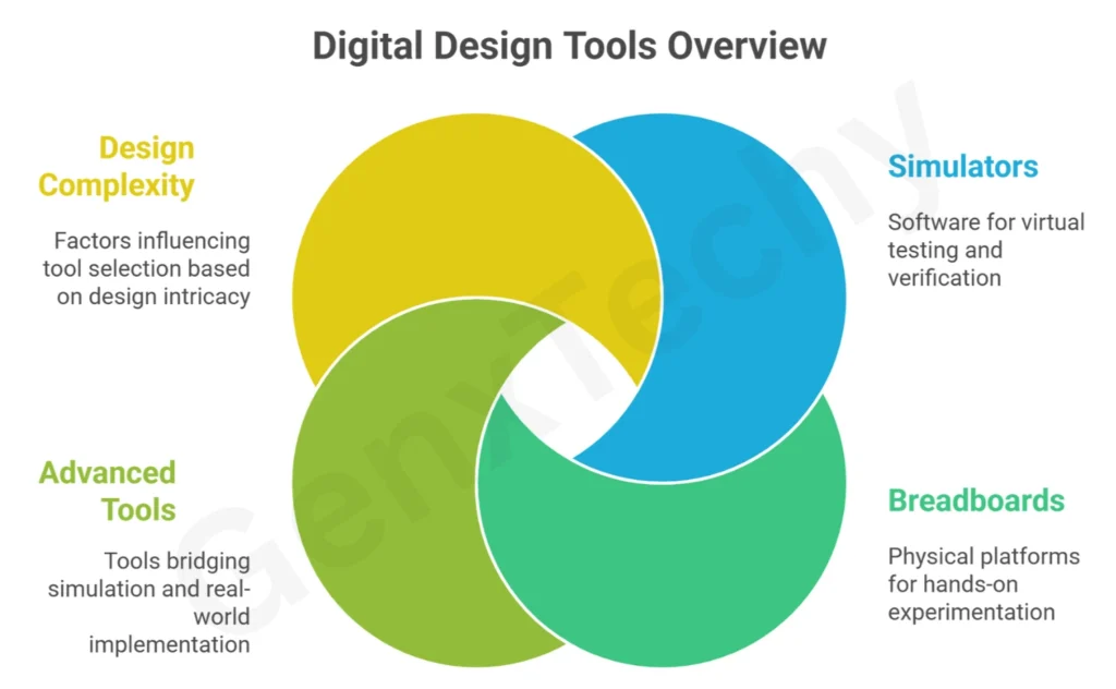
1. Digital design relies on a combination of simulators (for virtual testing) and breadboards (for physical prototyping).
2. Simulators like Logisim, ModelSim, and Vivado help verify logic, while breadboards and trainer boards allow hands-on experimentation.
3. Advanced tools like KiCad and logic analyzers bridge the gap between simulation and real-world implementation.
4. Choosing the right tools depends on the complexity of the design, from simple combinational circuits to complex FPGA-based systems.