Concept of Instruction Cycle, Machine Cycle and T-State
- The 8085 microprocessor fetches the instruction from the address in the program counter, decodes it, and then executes it. If needed, it fetches extra data before finishing execution.
- Each instruction has two parts: the opcode, which is the command (like ADD), and the operand, which is the data or register the command works on.
- The 8085 executes a program step by step, not all at once. These steps are explained using three terms: Instruction Cycle, Machine Cycle, and T-State.
Instruction Cycle
- The Instruction Cycle is the total time taken by the microprocessor to complete the execution of one instruction.
- An instruction can be simple (like MOV A, B) or more complex (like LDA 2500H).
- Every instruction cycle is made up of a sequence of machine cycles.
Machine Cycle
1. A Machine Cycle is the time taken by the microprocessor to complete one basic operation, such as:
- Fetching an opcode (Opcode Fetch Cycle)
- Reading data from memory (Memory Read Cycle)
- Writing data to memory (Memory Write Cycle)
- Reading data from an I/O device (I/O Read Cycle)
- Writing data to an I/O device (I/O Write Cycle
2. Each machine cycle consists of a fixed number of T-states (clock periods).
T-State (Clock Cycle)
- The T-state is the smallest unit of time in microprocessor operations.
- It is the time period of one clock pulse.
- Each machine cycle is made up of several T-states.
Example:
- If the clock frequency of 8085 is 3 MHz, then:
- Time for one T-state = 1 / 3 MHz = 333 nanoseconds.
- If a machine cycle takes 4 T-states, then total time = 4 × 333 ns = 1.333 microseconds.
T-state required for various machine cycles:
- Opcode Fetch Cycle – usually 4 to 6 T-states
- Memory Read Cycle – 3 T-states
- Memory Write Cycle – 3 T-states
- I/O Read Cycle – 3 T-states
- I/O Write Cycle – 3 T-states
- Interrupt Acknowledge Cycle – 3 T-states
Various possible states of the processor based on the control signals, IO/M’, S0 and S1:
Table 1: Processor States on different control signals
| IO/M’ | S1 | S0 | Processor State |
|---|---|---|---|
| Z (High Impedance) | 0 | 0 | Halt |
| 0 | 0 | 1 | Memory Write |
| 1 | 0 | 1 | I/O Write |
| 0 | 1 | 0 | Memory Read |
| 1 | 1 | 0 | I/O Read |
| 0 | 1 | 1 | Opcode Fetch |
| 1 | 1 | 1 | Interrupt Acknowledge |
Few facts about 8085 microprocessor machine cycle execution:
- The 8085 microprocessor takes four (4) T-states to execute the opcode fetch machine cycle.
- Three (3) T-states to execute the memory and I/O read/write cycles.
- The interrupt acknowledge cycle is similar to the opcode fetch cycle.
- Figure 1 shows the common waveform of the clock signal used in microprocessor systems. The clock signal is a square waveform of high frequency in the range of MHz.
- The rising and falling edge of the clock signal can be clearly seen, as its frequency is very high and time period is correspondingly very low.
- Timing diagram for an instruction is obtained by drawing the binary levels on the various signals of the 8085.
- It is drawn with respect to the clock input of the microprocessor. It explains the execution of the instruction using the basic machine cycles of that instructions.

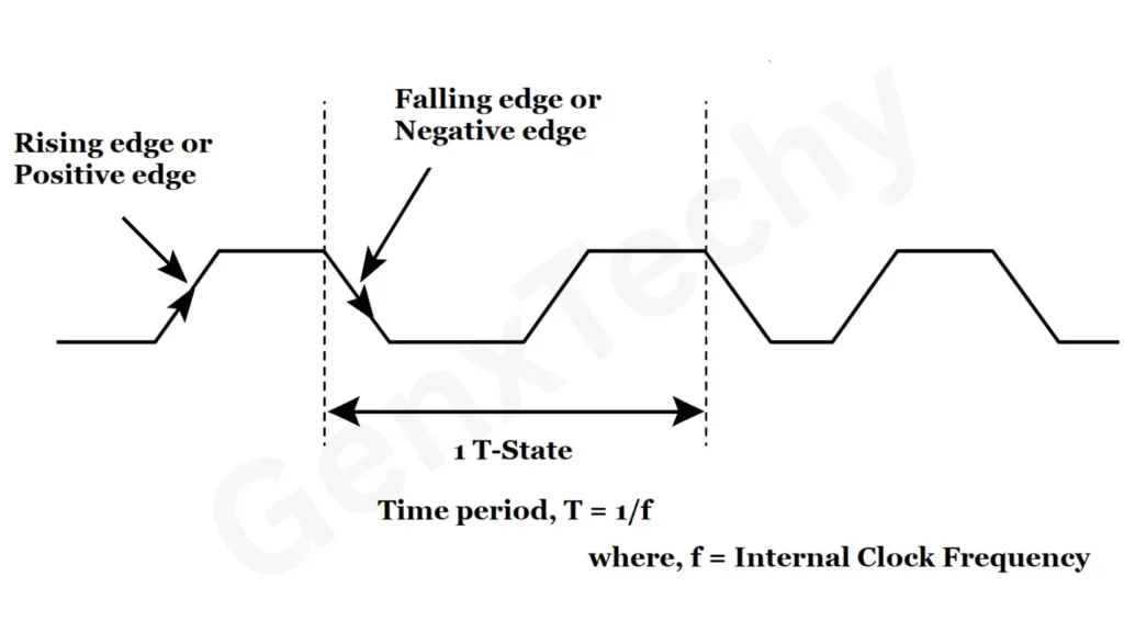
Fig. 1: waveform of the clock signal