What are Addressing Modes?
Different methods of instructing the microprocessor on where to locate the data it needs to work with are known as addressing modes. You may say “go to the blue house” or “go to house number 123” to guide someone to your house; both directions go to the same location but in different ways.
Addressing modes in the 8085 microprocessor are the several ways to indicate where an instruction should act on data. “Where should I store this result?” or “Where should I get this data from?” are questions the processor must answer.
Definition of Addressing mode:
Addressing modes in the 8085 are the rules that specify how and where the processor can find the operands (data) for an instruction. They define whether the data is in the instruction itself, in a register, in memory, or implied.
Why Do We Need Different Addressing Modes?
Imagine you’re cooking and need ingredients. Sometimes you already have salt in your hand (immediate), sometimes it’s in the jar on the counter (direct), and sometimes you need to check a recipe card that tells you which cabinet to look in (indirect). Similarly, data can be stored in different places, and we need different ways to access it efficiently.
Types of Addressing Modes in 8085 Microprocessor
An addressing mode is the method used by the 8085 microprocessor to specify the data (the operand) an instruction needs to work on. It’s the “how” and “where” the CPU finds this data.
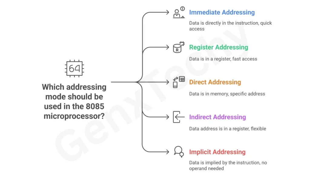
The 8085 has five (5) primary addressing modes.
(i) Immediate Addressing Mode
(ii) Register Addressing Mode
(iii) Direct Addressing Mode
(iv) Indirect Addressing Mode
(v) Implicit (or Implied) Addressing Mode
(i) Immediate Addressing Mode
In Immediate Addressing Mode, the data we want to use is written right inside the instruction. The processor does not go to any register or memory location to find it. It simply reads the next byte or bytes that follow the opcode and treats that as the operand.
Instruction format
- 8-bit immediate data: [Opcode] [8-bit data]
Example: MVI A, 32H
Here 3E is the opcode for MVI A, and 32 is the data byte.
- 16-bit immediate data: [Opcode] [Low byte] [High byte]
Example: LXI H, 2500H
Here 21 is the opcode, 00 is low byte, 25 is high byte.
In 8085, 16-bit immediate data appears low byte first, then high byte.
Effect of FLAG register:
Immediate operations that change A will also update flags:
- Arithmetic immediate instructions like ADI, SUI, ACI, SBI affect the following flag bits: Sign (S), Zero (Z), Auxiliary Carry (AC), Parity (P), Carry (CY) as per the result.
- Logical immediate instructions like ANI, ORI, XRI clear CY flag bit, and set AC flag bit only. In case of ANI instruction, update on flag bit like S, Z, P based on the result.
- CPI instruction compares the Accumulator (A) data with a given data in the instruction itself and sets flags like a subtraction without storing the result.
(ii) Register Addressing Mode
Register addressing mode is a method where the operand is taken from a register specified by the instruction.
In other words, Register addressing mode is when the operand needed by an instruction is already stored in one of the CPU registers. The instruction names the register or registers that hold the data. No memory access is needed to fetch the operand.
Detail of the registers are used in Register addressing mode
- In 8085 the common general-purpose registers are A, B, C, D, E, H, L.
- When an instruction refers to one of these registers, it is using register addressing mode.
- Note that M is not a register. M means memory addressed specified by HL register pair and so is not register addressing.
Instruction format
Most register-addressing instructions are just one opcode byte that encodes the registers involved. Typical formats include:
- MOV Destination, Source
Example: MOV B, C
Operation: copy content of register C into register B.
- ADD r
Example: ADD C
Operation: A ← A + C.
Note: Accumulator is the by default register for most of the arithmetic operations.
- SUB R, ANA R, XRA R, ORI R, CMP R and similar all operate on registers named in the opcode.
- INR R, DCR R increment or decrement the register R.
Effect of FLAG register:
- MOV instructions do not affect any flag bits.
(iii) Direct Addressing Mode
In direct addressing mode the instruction itself contains the 16-bit memory address of the operand. The CPU reads that address from the instruction, then goes to that exact memory location to fetch or store data.
Instruction format
For instructions that use direct addressing the binary/hex encoding holds the address in two bytes. The format is:
[OPCODE] [low-order byte of address] [high-order byte of address]
- The 8085 stores the low-order byte first, then the high-order byte. Most direct-address instructions are 3 bytes long.
Example:
LDA 2500H
Here 3A is the opcode for LDA, 00 is the low-order byte of 2500H, and 25 is the high-order byte.
Common direct-address instructions
- LDA 16-bit address: Load accumulator from memory [16-bit address]
- STA 16-bit address: Store accumulator to memory[16-bit address]
- LHLD 16-bit address: Load HL pair from memory [addr] (L <- memory[addr], H <- memory[addr+1])
- SHLD 16-bit address: Store HL pair into memory [16-bit address] and memory[16-bit address+1] (L -> 16-bit address, H -> 16-bit address+1)
- JMP 16-bit address / JZ 16-bit address / JNZ 16-bit address / JC 16-bit address / JNC 16-bit address: Unconditional and conditional jumps to the given address
- CALL 16-bit address: Call a subroutine at the given address (CALL pushes return address on the stack)
Effect of FLAG register:
- Data transfer instructions that use direct addressing (LDA, STA, LHLD, SHLD) do not affect the flags.
- Conditional jumps and calls test flags to decide whether to branch, but the jump instructions themselves do not modify flags.
(iv) Indirect Addressing Mode
In indirect addressing mode the instruction does not give the operand directly. Instead it gives a register pair whose contents hold the memory address of the operand. The CPU uses that register pair as a pointer and accesses memory at the address stored in the pair.
Execution of Indirect Addressing mode
Think of a register pair (for example HL) as a pointer variable that stores a memory address. When an instruction uses indirect addressing, the processor reads the register pair, gets the address out of it, and then reads or writes memory at that address. We never write the memory address directly in the instruction. We only mention which pointer (which register pair) to use.
Common pointer registers and Memory Pointer (M)
- The HL register pair is the usual pointer used with the notation M. When an instruction uses M it means memory at address held by HL.
For example, MOV A, M means load A from memory pointed to by HL.
- The BC and DE pairs can also act as pointers, but only with specific instructions: LDAX B and LDAX D, the instruction Load (read) accumulator (A) from memory pointed by BC or DE respectively.
- Similarly, STAX B and STAX D store accumulator (A) into memory pointed by BC or DE.
Note that M is not a register. It is shorthand for memory addressed specified by HL register pair.
Instruction format
Most register-indirect instructions are one byte long. There are no address bytes following the opcode because the address comes from a register pair at runtime. Few examples of indirect instructions are: