Embedded systems power many modern technologies, from smartphones to smart appliances, making their design both important and challenging. To ensure efficiency and reliability, engineers follow a structured design methodology that guides the system from initial concept to final implementation. This process involves key stages such as specification, hardware-software partitioning, synthesis, and simulation. By carefully balancing hardware and software components, designers can meet constraints like cost, power, and performance. Understanding this methodology helps bridge the gap between theory and real-world system design.
Let’s walk through this methodology in a detailed as shown in Figure 9.1, human-friendly way so that students and beginners can truly understand how real-world embedded systems are designed.
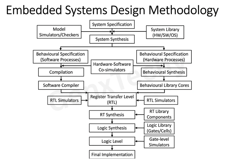
Fig. 9.1: Embedded Systems Design Methodology
1. System Specification: The Starting Point of Innovation
Every embedded system begins with a clear system specification. Think of this as the blueprint or vision document where all requirements are defined.
At this stage, engineers ask questions like:
- What problem are we solving?
- What inputs and outputs are expected?
- What are the performance constraints (speed, power, cost)?
- What environment will the system operate in?
For example, if you’re designing a smart temperature controller, the specification would include sensor types, response time, accuracy, and communication protocols.
Along with this, designers often rely on a system library (Hardware/Software/Operating System). This library contains reusable components such as:
- Prebuilt hardware modules
- Software routines
- Operating system elements
Using these libraries saves time and ensures reliability.
Additionally, model simulators/checkers are used early on to validate whether the proposed system concept behaves correctly before moving further.
2. System Synthesis: Dividing the Brain and Body
Once the system requirements are clear, the next step is system synthesis. This is where the system is divided into:
- Hardware components
- Software components
This partitioning is crucial because not everything should be implemented in hardware or software alone. Designers must decide:
- What should run as software (flexible, easier to update)?
- What should be implemented in hardware (faster, more efficient)?
For instance:
- Complex calculations → hardware (for speed)
- User interface logic → software (for flexibility)
This step leads to two parallel paths:
a) Behavioural specification for software processes
b) Behavioural specification for hardware processes
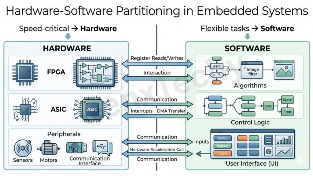
Fig 9.2: Hardware – Software partitioning in Embedded Systems
3. Behavioural Specification: Defining How Things Work
At this stage, the system is described in terms of behavior, not implementation.
a) Software Behavioural Specification
This defines how the software behaves:
- Algorithms
- Control flow
- Data processing logic
It is usually written in high-level programming languages like C or Python.
To ensure correctness, hardware-software co-simulators are used. These tools allow both hardware and software to be tested together virtually, ensuring smooth interaction.
b) Hardware Behavioural Specification
Here, hardware functionality is described at a higher abstraction level using languages like:
- VHDL
- Verilog
Instead of circuits, designers describe:
- What the hardware should do
- How data flows
Designers also use behavioural library cores, which are pre-designed modules like:
- Multipliers
- ALUs
- Controllers
This speeds up development significantly.
4. Compilation and Behavioural Synthesis
Now the design begins to take a more concrete form.
a) Software Side
The behavioural description is passed through a software compiler, converting high-level code into:
- Machine code or assembly
- Instructions for the processor
b) Hardware Side
The behavioural description undergoes behavioural synthesis, which converts it into:
- Register Transfer Level (RTL) specification
This is a key transition point. RTL defines:
- Data movement between registers
- Control signals
- Timing behavior
5. Register Transfer Level (RTL): The Heart of Digital Design
RTL is where abstract ideas become structured digital logic.
At this level:
- The system is described in terms of registers, buses, and operations
- Timing and synchronization become important
Both hardware and software paths converge here conceptually, ensuring consistency.
To validate this stage, RTL simulators are used. These simulators check:
- Logical correctness
- Timing behavior
- Functional accuracy
This step helps catch errors early before moving to physical implementation.
6. RT Synthesis: Moving Towards Real Hardware
Next, the RTL design is transformed using RT synthesis tools into a logic-level specification.
This process maps:
- RTL descriptions → actual logic components
Designers also use RT library components, which include:
- Registers
- Multiplexers
- Arithmetic units
This stage ensures that the design is feasible using available hardware resources.
7. Logic Level Design: Building with Gates
At this stage, the system is expressed using:
- Logic gates (AND, OR, NOT, etc.)
- Standard cells
The logic synthesis tool converts the design into a gate-level netlist using a logic library (gates/cells).
This is a crucial step because:
- It directly impacts performance
- It determines power consumption
- It affects chip area
To verify correctness, gate-level simulators are used. These provide:
- Accurate timing analysis
- Signal propagation details
8. Simulation at Every Stage: Reducing Risk
One of the most important aspects of this methodology is continuous simulation.
Simulation occurs at:
- System level
- Behavioural level
- RTL level
- Gate level
This layered verification ensures:
- Early error detection
- Reduced development cost
- Higher reliability
Instead of discovering problems after manufacturing (which is expensive), designers fix issues during simulation.
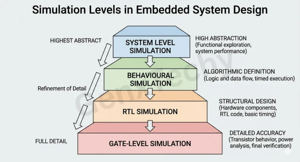
Fig 9.3: Simulation at Every Stage of Embedded System Design
9. Final Implementation: Bringing the System to Life
After passing all stages of synthesis and simulation, the system reaches final implementation.
This could involve:
- Fabricating an ASIC (Application-Specific Integrated Circuit)
- Programming an FPGA
- Deploying software on a microcontroller
At this stage, the embedded system becomes a physical reality.
For example:
- A smart home controller
- An automotive Electronic Control Unit (ECU)
- A wearable health device
Putting It All Together
The embedded systems design methodology is a carefully layered process that ensures efficiency, accuracy, and reliability. By moving from abstract specifications to concrete implementations—while continuously validating at each stage—engineers can design robust systems that power everything from smartphones to industrial machines.
Understanding this flow not only helps students academically but also prepares them for real-world engineering challenges where precision and optimization are critical.