(a) Binary to Gray Code Converter
(b) Gray to Binary Code Converter
Design of a 4-bit Binary-to-Gray Code Converter
Step-1: Clearly Define the Conversion Requirement
First, identify:
- Input Code: Binary
- Output Code: Gray
- Number of Bits: 4-bit
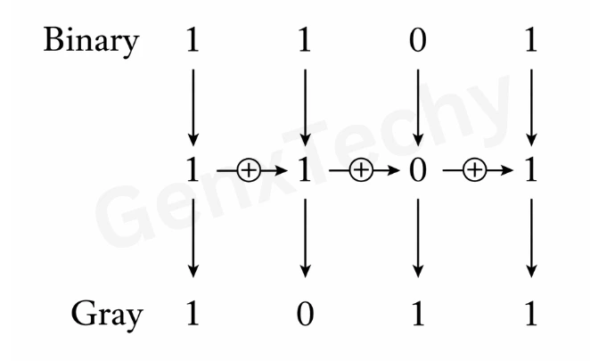
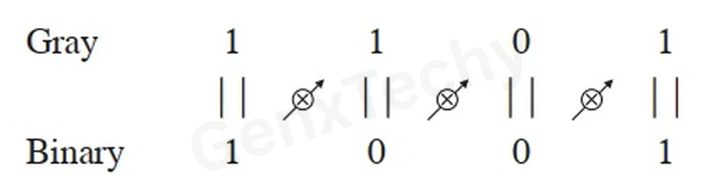
Example: Convert the binary 1101 to the Gray code
Input Variables: B4, B3, B2, B1
Output Variables: G4, G3, G2, G1
Step-2: Construct the Conversion Table
- The input to the 4-bit binary-to-Gray code converter circuit is a 4-bit binary and the output is a 4-bit Gray code.
- There are 16 possible combinations of 4-bit binary input and all of them are valid.
- Hence no don’t cares.
- The 4-bit binary and the corresponding Gray code are shown in the conversion
- table 1, shown below.
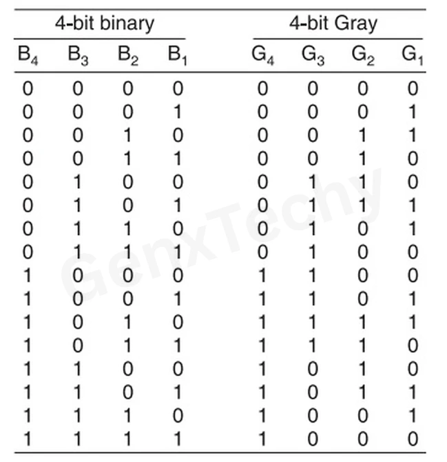
Table 1: 4-bit Binary to Gray code conversion
Step-3: Derive Boolean Expressions for Each Output Bit
From the conversion table, it is observed that the expressions for the outputs G4, G3, G2, and G1 are as follows:
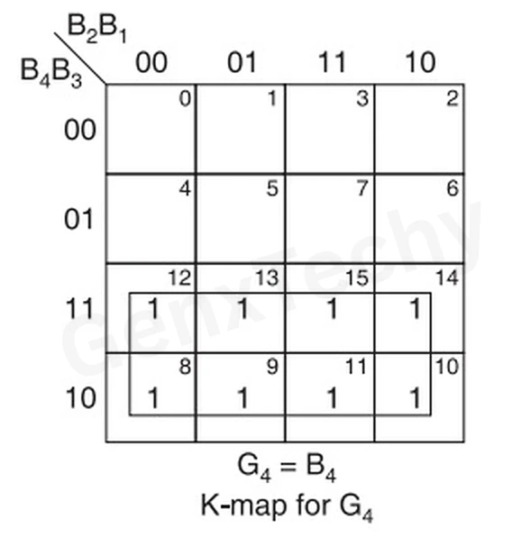
G4 = ∑m(8, 9, 10, 11, 12, 13, 14, 15)
G3 = ∑m(4, 5, 6, 7, 8, 9, 10, 11)
G2 = ∑m(2, 3, 4, 5, 10, 11, 12, 13)
G1 = ∑m(1, 2, 5, 6, 9, 10, 13, 14)
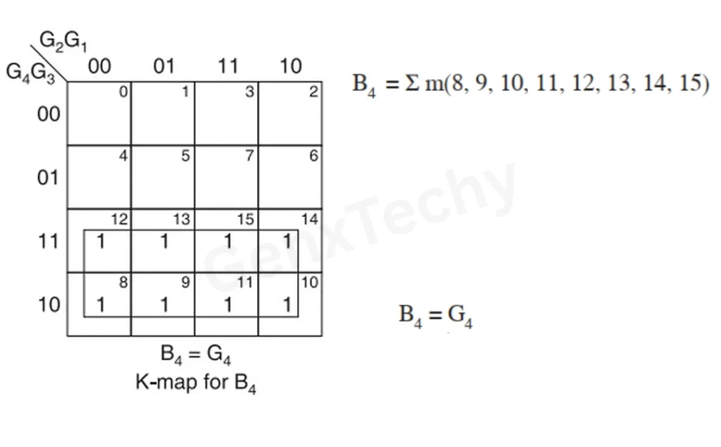
Step-4: Simplify the output functions Using K-Map
K-map for G4 = ∑m(8, 9, 10, 11, 12, 13, 14, 15)
K-map for G3 = ∑m(4, 5, 6, 7, 8, 9, 10, 11)
K-map for G2 = ∑m(2, 3, 4, 5, 10, 11, 12, 13)
 K-map for G1 = ∑m(1, 2, 5, 6, 9, 10, 13, 14)
Step-5: Implement the Logic Circuit
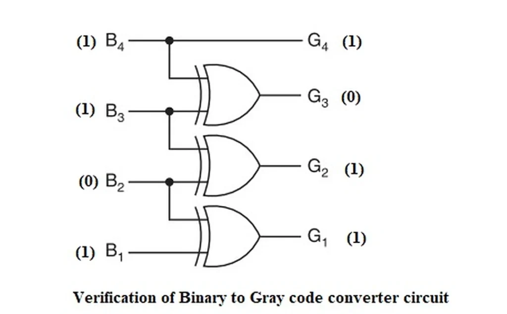
Using the simplified Boolean equations, draw the final logic diagram for 4-bit Binary-to-Gray Code Converter circuit using the AND, OR, NOT and XOR gates, as shown below:
Step-6: Verify the Design
Verification ensures the converter works correctly. To verify the circuit diagram, random binary inputs are given such as (1, 1, 0, 1) and the outputs given by the design circuit are (1, 0, 1, 1). Hence, proved that the designed logic circuit is correct.
Design of a 4-bit Gray-to-Binary Code Converter
Step-1: Clearly Define the Conversion Requirement
First, identify:
- Input Code: Gray code
- Output Code: Binary
- Number of Bits: 4-bit
Example: Convert the Gray code ‘1101’ to the Binary code
Input Variables: G34, G3, G2, G1
Output Variables: B4, B3, B2, B1
Step-2: Construct the Conversion Table
- The input to the 4-bit Gray-to-Binary code converter circuit is a 4-bit Gray code and the output is a 4-bit Binary code.
- There are 16 possible combinations of 4-bit Gray input and all of them are valid.
- Hence no don’t cares.
The 4-bit Gray code and their corresponding Binary code are shown in the conversion
table 2, shown below.
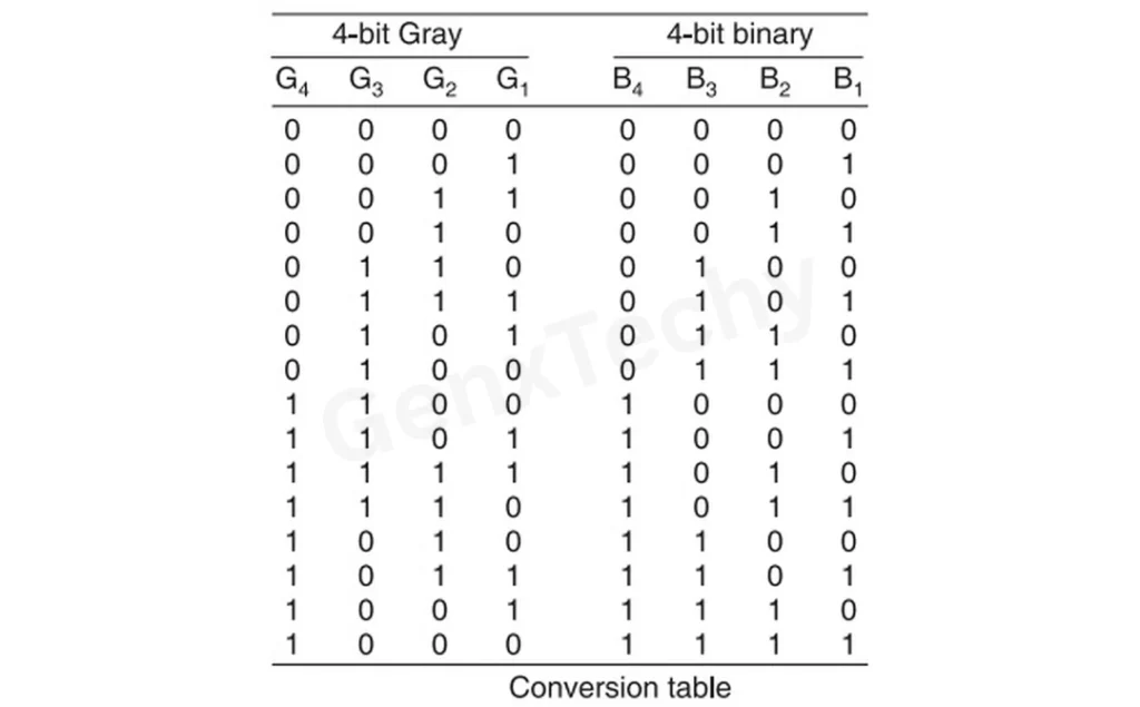
Table 2: 4-bit Gray to Binary code conversion
Step-3: Derive Boolean Expressions for Each Output Bit
From the conversion table, it is observed that the expressions for the outputs B4, B3, B2, and B1 are as follows:
B4 = ∑m(8, 9, 10, 11, 12, 13, 14, 15)
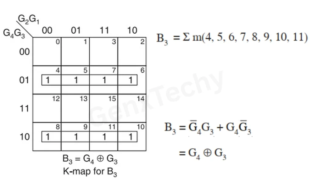
B3 = ∑m(4, 5, 6, 7, 8, 9, 10, 11)
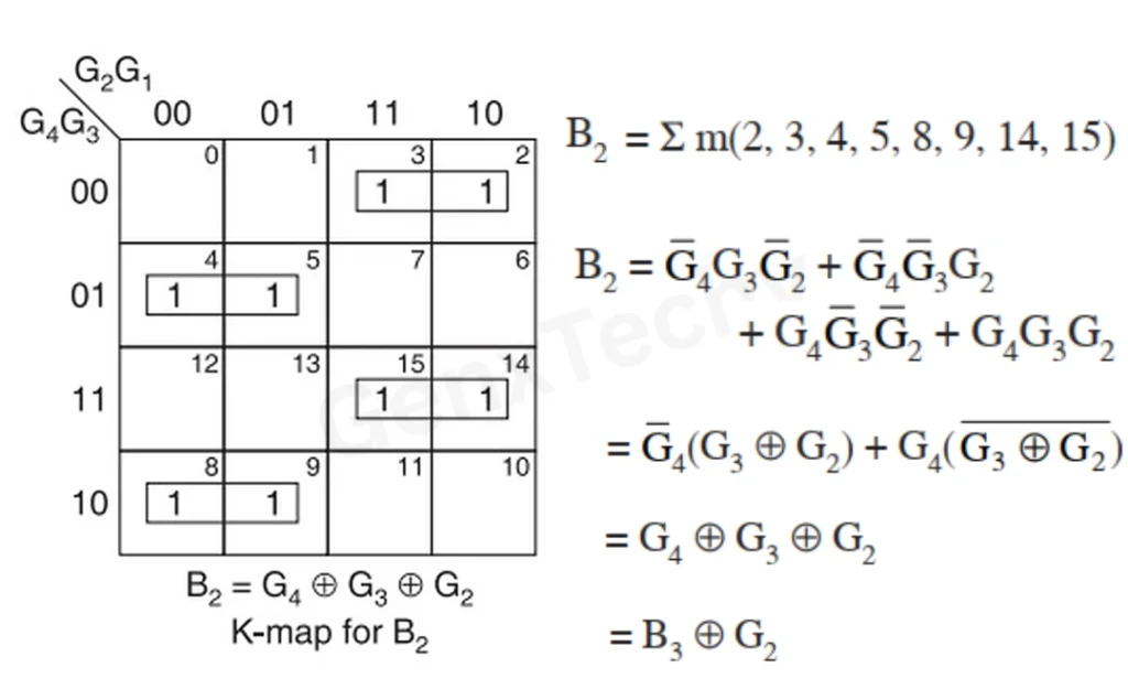
B2 = ∑m(2, 3, 4, 5, 8, 9, 14, 15)
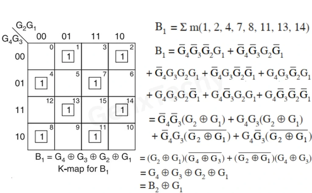
B1 = ∑m(1, 2, 4, 7, 8, 11, 13, 14)
Step-4: Simplify the output functions Using K-Map
K-map for B4 = ∑m(8, 9, 10, 11, 12, 13, 14, 15)
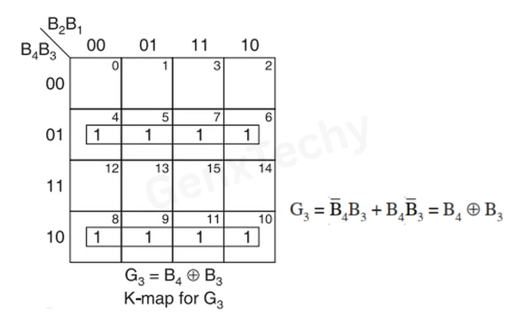
K-map for B3 = ∑m(4, 5, 6, 7, 8, 9, 10, 11)
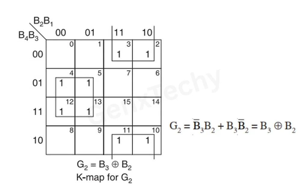
K-map for B2 = ∑m(2, 3, 4, 5, 8, 9, 14, 15)
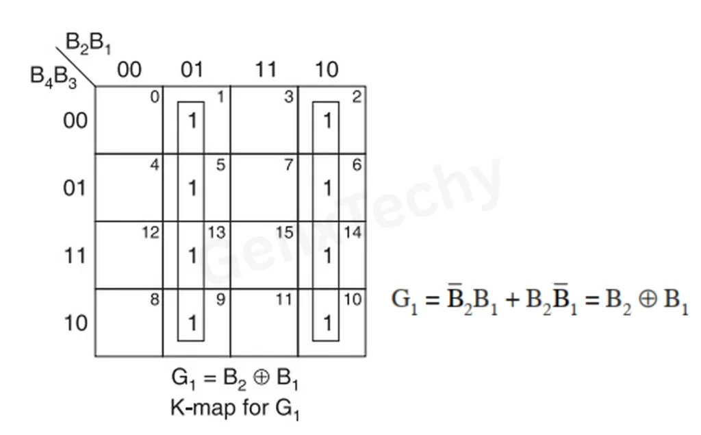
K-map for B1 = ∑m(1, 2, 4, 7, 8, 11, 13, 14)
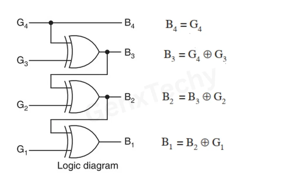
Step-5: Implement the Logic Circuit
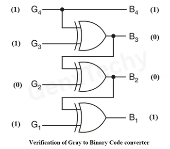
Using the simplified Boolean equations, draw the final logic diagram for 4-bit Gray-to-Binary Code Converter circuit using the AND, OR, NOT and XOR gates, as shown below:

Step-6: Verify the Design
Verification ensures the converter works correctly. To verify the circuit diagram, random 4 bit Gray inputs are given such as (1, 1, 0, 1) and the outputs given by the design circuit are (1, 0, 1, 1). Hence, proved that the designed logic circuit is correct.