The bus structure of the 8085 microprocessor is shown in Figure 1. It is divided into three categories: Address bus, Data bus, and Control bus. The Address bus and Data bus were discussed in Part 1, while this section focuses on the Control bus.
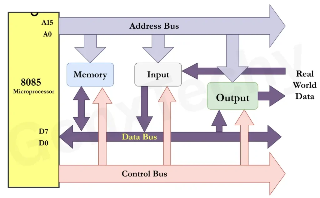
Fig. 1: Bus Structure of 8085 Microprocessor
iii) Control Bus
The control bus consists of a set of individual lines designed to carry control signals that are used to control and synchronize operations of the microprocessor as it interacts with memory and peripheral devices. These control signals ensure that the microprocessor and peripheral devices operate in a synchronized manner and perform the correct operations at the correct times.
Control signals are classified into:
i) Control & Status Signals
ii) DMA (Direct Memory Access) Control Signals
iii) Interrupt Control Signals
iv) Ready Signal
v) Reset Signals
1) Control & Status Signals:
These indicate the type of operation and manage data flow.
a) RD’ (Read)’: This control signal indicates that the microprocessor is executing a read operation. When the RD’ signal is activated that is logic 0 is applied, it signifies that data is being read from the memory or an I/O device onto the data bus.
b) WR’ (Write)’: The WR’ signal is used for write operation by the microprocessor. When WR’ signal is active that is logic 0 is applied, the microprocessor writes data from the data bus to a memory location or an I/O device.
c) ALE (Address Latch Enable): The ALE signal is very important when demultiplexing the address/data bus. The lower 8 bits of the address bus are multiplexed with the data bus and forms AD0 to AD7.
ALE signal goes high for the first clock pulse of a machine cycle to latch the lower 8 bits of the address into an external latch, then the bus can be used to transfer data.
d) IO/M’ (Input/Output – Memory): This signal is used to differentiate between memory and I/O operations.
Whenever IO/M’ is low (logic 0), it is a memory operation, and whenever it is high (logic 1), it is an I/O device operation.
e) S1 and S0: These are status signals used internally by the microprocessor to define the type of operation being carried out (e.g., opcode fetch, memory read/write, I/O read/write).
ii) DMA (Direct Memory Access) Control Signals:
DMA control signals are utilized for direct data transfer from memory to the I/O, and vice versa, with no involvement from the CPU.
a) HOLD Signal: A HOLD signal is used by an external device to request control of the buses (Address Bus, Data Bus and Control Bus) of the microprocessor.
The operation of the HOLD signal:
- An external device (for example, DMA controller) wants to transfer data directly to/from memory.
- Typically, it would send a HOLD signal to the microprocessor.
- This signal will inform the 8085 that another device wants to take control of the buses.
- The microprocessor checks the HOLD signal at the end of the current machine cycle, but does not interrupt an instruction that is in progress.
- After a HOLD request, the first thing the microprocessor will do is complete the current instruction.
- The microprocessor will then release the buses to the requesting device.
- During this time when another device has control of the buses, the microprocessor does not perform, and will not perform any memory or I/O operations – it is in bus hold state
b) HLDA (Hold Acknowledge) Signal: This signal is used by the microprocessor to confirm that the HOLD request has been received and to inform the external device that the buses are now released and available for use.
The operation of the HLDA signal:
- When the 8085 microprocessor receives the HOLD signal and completes its current instruction, it sends a logic “high” HLDA to the device who requested the bus in response to the HOLD signal.
- The HLDA signal acknowledges to the external device that it may now use the system buses for its operation.
- HLDA remains active while HOLD is active.
Bus Control Return:
- Once the external device is finished and releases the HOLD signal, the microprocessor again turns off the HLDA and regains control of the buses.
iii) Interrupt Control Signals:
Interrupt control signals processes external requests to interrupt the CPU execution.
a) INTR (Interrupt Request):
- INTR (Interrupt Request) is a maskable, vectored interrupt input signal in the 8085 microprocessor.
- INTR is an input used by external devices to request that the CPU suspend execution temporarily and service the interrupting device.
b) INTA’ (Interrupt Acknowledge):
- The INTA’ signal is used to indicate that the microprocessor has recognized an interrupt request.
- The microprocessor sends the INTA’ signal out as an acknowledgment to the interrupting device when the interrupt is acknowledged.
iv) Ready Signal:
The READY signal is an input control sign in the 8085 microprocessor. It allows the operation of the CPU(s) to be initially synchronized with a slower device memory or input/output.
- Active Level: Logic High (1) means “ready”, Logic Low (0) means “not ready”
- If READY = 1 → The CPU proceeds normally with the current machine cycle.
- If READY = 0 → The CPU inserts wait states between T-states (clock cycles) until READY goes high.
- Requirement of Ready signal:
i) To insert wait states if memory or I/O device is too slow to respond at CPU clock speed.
ii) The 8085 microprocessor can run faster than some peripherals or memory chips.
- Without the READY signal, the CPU may read/write before the device is ready for the transaction and the data transfer will be incorrect.
- READY will ensure the CPU will wait until a device is ready to transfer
v) Reset Signals:
- Reset control signals are utilized in the 8085 microprocessor to initialize the system and bring both the CPU and the attached peripherals into a known, stable state before the CPU begins normal operations.
- These signals determine if the hardware has powered up properly, if the system has recovered from an error or rebooted during operation, or initiates a re-initialization.
The reset control signals in the 8085 are:
a) RESET IN
- Reset In is an input signal to the microprocessor.
- It is an active High (logic 1) signal.
- If the signal is active, the microprocessor will reset and initializes it to a known starting state.
- Function of Reset In:
i) Once Reset In has been active for a minimum of three clock cycles, the CPU will do the following:
- Clear the Program Counter (PC) → CPU will execute starting from 0000H.
- Clear the instruction register and all status flags.
- Disable all interrupts.
ii) Generally, it is connected to an external reset circuit such as the one of the following:
- Power-on Reset circuit (turns on when the system is first powered up).
- Manual Reset switch.
- When Reset In is active, the microprocessor will remain in the reset state until the signal is turned off and will not execute any instructions.
b) RESET OUT
- Reset Out is an output signal to the microprocessor.
- It is a logic High (logic 1) signal.
- The activation of this signal notifies other devices that the CPU is being reset.
Function of Reset Out:
- Reset Out goes high whenever Reset In is high.
- It will reset peripheral devices, memory, and other components of the system in order to come up in sync with the CPU.
- A signal generated internally by the CPU and is active as long as Reset In is active.
Figure 2 summarizes all the control and status signals of 8085 microprocessor.
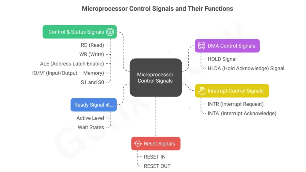
Fig. 2: Control and Status Signals of 8085 Microprocessor.