An encoder is a digital device that converts familiar numbers, decimal digits, or alphabetic characters into a coded representation suitable for digital systems. In practical digital electronics, most systems operate using binary codes rather than decimal or symbolic data. Therefore, an encoder serves as an interface between human-readable information and machine-readable binary format. In simple terms, it translates commonly used symbols into their corresponding binary codes so that digital circuits can process them efficiently.
- An encoder is a combinational circuit whose output depends only on the current inputs. It uses basic logic gates, requires no memory or clock, and produces an immediate output for any input change.
- An encoder performs the reverse operation of a decoder. While a decoder converts binary code into a specific output, an encoder converts one active input into its corresponding binary code. Encoding converts familiar symbols into coded form, whereas decoding restores the original information.
- An encoder has multiple input lines and fewer output lines, related by M=2N. An N-bit output can represent up to 2N (M) input conditions. For example, a 4-to-2 or 8-to-3 encoder converts many inputs into fewer outputs, effectively compressing information.
- Basic block diagram of encoder circuit is shown below:
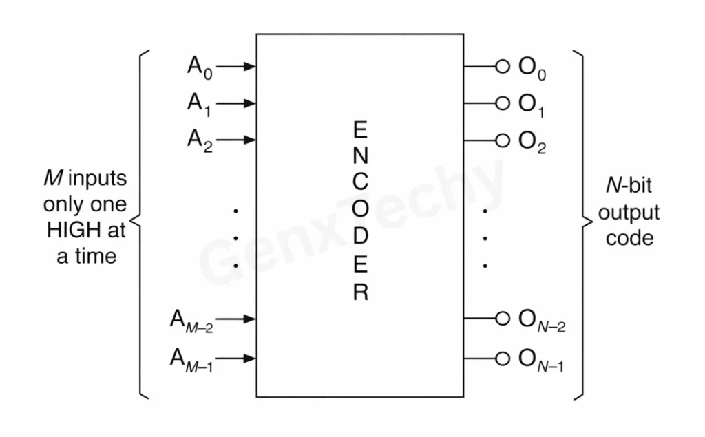
Fig. 1: Block diagram of encoder
Octal-to-Binary Encoder
An Octal-to-Binary Encoder is a combinational circuit that converts 8 input lines into a 3-bit binary output. Since octal digits range from 0 to 7, three binary bits are sufficient to represent them.
Thus,
8 = 23
So, it is also called an 8-to-3 encoder.
The block diagram of 8-to-3 encoder is shown in figure 2.
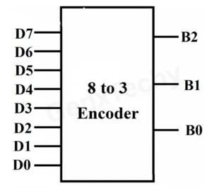
Fig. 2: Block diagram of 8-to-3 encoder
The encoder has:
- 8 input lines: D₀, D₁, D₂, D₃, D₄, D₅, D₆, D₇
- 3 output lines: B₂, B₁, B₀
Only one input is assumed to be HIGH at a time.
Truth table of 8-to-3 encoder is shown in table 1:
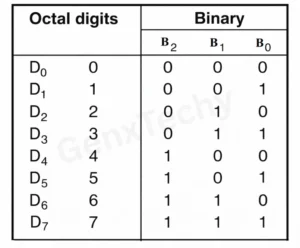
Table 1: Truth table of Octal to Binary Encoder
From the truth table, it is observed that B2 is a 1 if any of the digits D4 or D5 or D6 or D7 is a 1. Similarly, B1 is a 1 if any of the digits D2 or D3 or D6 or D7 is a 1. And B0 is a 1 if any of the digits D1 or D3 or D5 or D7 is a 1. The output is formulated as:
B2 = D4 + D5 + D6 + D7
B1 = D2 + D3 + D6 + D7
B0 = D1 + D3 + D5 + D7
As D0 is not present in any of the expressions. So, D0 is a don’t care and can be ignored in the circuit diagram. Figure 3 shows the logic circuit for an octal-to-binary encoder with active HIGH inputs.
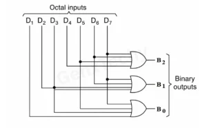
Fig. 3: Logic diagram of 8-to-3 encoder
Decimal-to-BCD Encoder
A Decimal-to-BCD Encoder is a combinational circuit that converts 10 input lines into a 4-bit BCD output. Since decimal digits range from 0 to 9, four binary bits are sufficient to represent them
So, it is also called a 10-to-4 encoder.
The block diagram of 10-to-4 encoder is shown in figure 4.
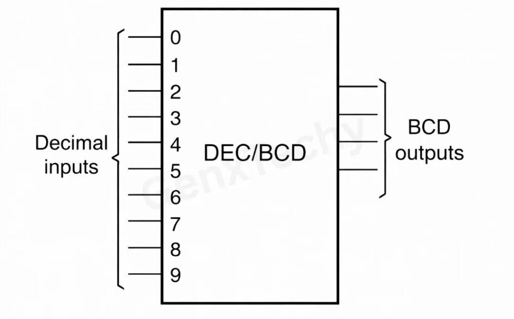
Fig. 4: Block diagram of 10-to-4 encoder
The encoder has:
- 10 input lines: D₀, D₁, D₂, D₃, D₄, D₅, D₆, D₇, D8, D9
- 3 output lines: B3, B₂, B₁, B₀
Only one input is assumed to be HIGH at a time.
Truth table of 10-to-4 encoder is shown in table 2:
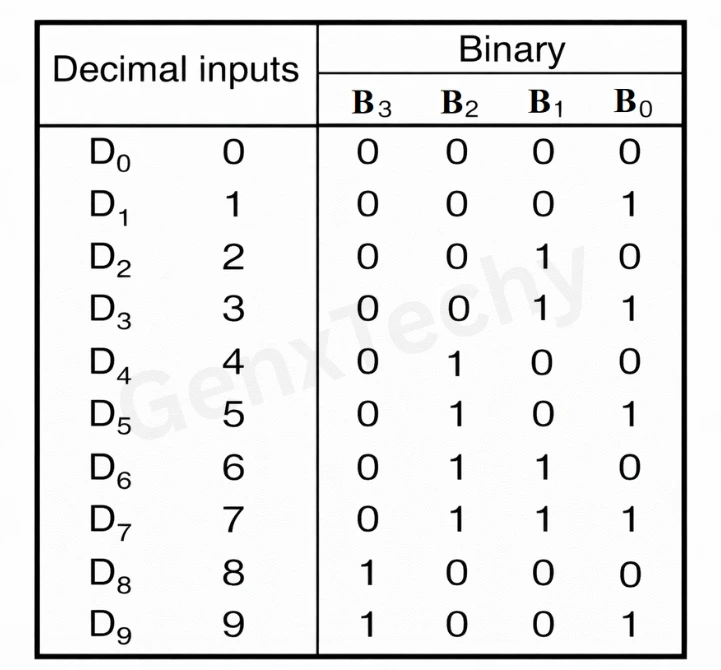
Table 2: Truth table of Decimal to BCD Encoder
From the truth table, it is observed that B3 is a 1 if any of the digits D8 or D9 is a 1. Similarly, B2 is a 1 if any of the digits D4 or D5 or D6 or D7 is a 1. The output, B1 is a 1 if any of the digits D2 or D3 or D6 or D7 is a 1. And B0 is a 1 if any of the digits D1 or D3 or D5 or D7 or D9 is a 1. The output equation to design the logic diagram for decimal to BDC is given below:
B3 = D8 + D9
B2 = D4 + D5 + D6 + D7
B1 = D2 + D3 + D6 + D7
B0 = D1 + D3 + D5 + D7 + D9
As D0 is not present in any of the expressions. So, D0 is treated as don’t care and can be ignored from the circuit diagram. Figure 5 shows the logic circuit for a decimal-to-BCD encoder with active HIGH inputs.
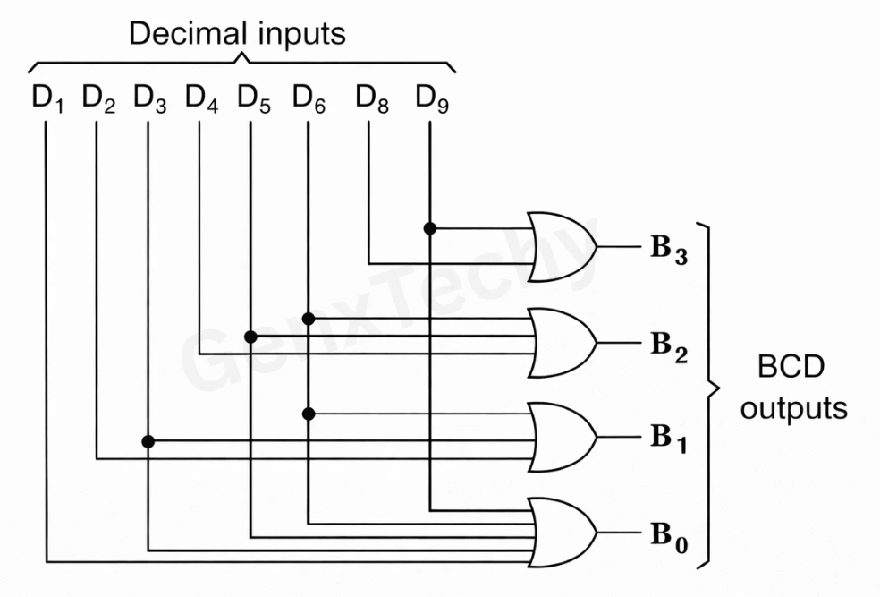
Fig. 5: Logic diagram of decimal-to-BCD encoder